The signal ground (SG) is a sensor of various physical quantities, a zero potential of the signal source, and a common reference ground (relative zero potential) of the signals in the circuit.
Here, the signal generally refers to an analog signal or a weak digital signal, which is susceptible to fluctuations in power supply or external factors, resulting in a decrease in the signal-to-noise ratio (SNR) of the signal. Especially the analog signal, the drift of the signal ground, will lead to a decrease in the signal-to-noise ratio; the measured value of the signal will produce errors or errors, which may lead to system design failure.
Therefore, the requirements for the signal ground are high, and special processing is needed in the system to avoid direct connection with high-power power ground, digital ground, and easily generated interference ground. Especially for the measurement of small signals, the signal ground usually needs to be isolated.
Main purpose of signal circuit grounding and power grounding
1. Protect the safety of the person and equipment, and prevent the outer casing from being charged when the insulation of the electrical device is damaged. There is a danger of electric shock when people touch it;
2. System operation needs, such as neutral point grounding of AC power system, positive or neutral grounding of power supply in DC system. The purpose of signal circuit grounding is to ensure that the signal has a stable reference potential.
In order to make the electronic equipment work with a uniform reference potential, to avoid the interference of harmful electromagnetic fields, and to make the electronic equipment work stably and reliably, the signal circuit in the electronic equipment should be grounded, referred to as signal ground.
What is the difference between signal grounding and power grounding?
The power ground is mainly for the path taken by the power loop current. Generally, the current flowing through the power supply is large, and the signal ground is mainly for the return of the communication signal between the two chips or modules. Path, in general, the current flowing through the signal is very small. In fact, both are GND. The reason is that you want to understand that when you are laying PCB board, you must clearly understand the flow of power and signal return. Path, then consider how to avoid the power supply and signal sharing return path when laying out. If it is shared, it may cause a large current on the power ground to generate a voltage difference on the signal ground (can be explained as: the wire is impedance, just Very small resistance, but if the current flowing is large, it will also produce a potential difference on this wire, which is also called common impedance interference), so that the true potential of the signal ground is higher than 0V, if the potential of the signal ground When it is large, it may cause the signal to be high level, but it is misjudged as low level.
Of course, the power supply is inherently unclean, and this avoids misjudging the signal due to interference. So take a little attention to both wiring, you can. Generally speaking, even if they are together, there will be no big problem because the threshold of the digital circuit is high.
Signal line shielding layer grounding method and principle
One end of the shielded wire is grounded and the other end is suspended. When the transmission distance of the signal line is relatively long, the grounding resistance at both ends is different or there is current on the PEN line, which may cause the potentials of the two grounding points to be different. At this time, if the two ends are grounded, the shielding layer has current flowing, but the signal is opposite. Interference is formed, so in this case, one grounding is generally used, and the other end is suspended to avoid such interference. The grounding shielding at both ends is better, but the signal distortion will increase.
Please note: the two-layer shield should be insulated and shielded from each other! If not insulated from each other, it should be treated as a single layer shield!
The grounding of the outermost shield is induced by the potential difference introduced, thereby generating a magnetic flux that reduces the strength of the source magnetic field, thereby substantially canceling the voltage induced when there is no outer shield; and the innermost shield is grounded at one end. Because there is no potential difference, it is only used for general anti-static induction. The following specifications are evidence:
"GB 50217-1994 Power Engineering Cable Design Specification" - 3.6.8 The grounding method of the control cable metal shield shall comply with the following provisions:
(1) The analog signal loop control cable shielding layer of the computer monitoring system shall not constitute two or more points of grounding, and it is recommended to use a centralized one-point grounding.
(2) In addition to the (1) item and other control cable shielding layers that require a little grounding, when the electromagnetic induction interference is large, two points of grounding should be used; the electrostatic induction interference is large, and one point can be grounded. For double shield or composite general shield, it is better to use one point for the inner and outer shields and two points for grounding.
(3) The choice of two-point grounding should also consider that the shielding layer will not be melted under the action of transient current.
"GB50057-2000 Building Lightning Protection Design Code" - Article 6.3.1 stipulates: ... When shielded cable is used, its shielding layer should be equipotentially connected at least at both ends. When the system requires only equipotential bonding at one end. Two layers of shielding shall be used, and the outer shielding shall be treated as described above.
The principle is as follows: 1. The single-layer shield is grounded at one end, and no potential difference is formed, which is generally used for anti-static induction. 2. Double-layer shielding, the outermost shield is grounded at both ends, and the inner shield is equipotentially grounded at one end. At this time, the outer shield induces a current due to the potential difference, thereby generating a magnetic flux that reduces the strength of the source magnetic field, thereby substantially canceling the voltage induced when there is no outer shield.
If it is to prevent static interference, it must be grounded at a single point, whether it is one layer or two layers. Because the electrostatic discharge rate of single point grounding is the fastest.
However, the following two cases are excluded:
1. There is strong current interference outside, and single point grounding cannot meet the fastest discharge of static electricity.
If the grounding wire has a large cross-sectional area and can ensure the fastest discharge of static electricity, it must also be grounded at a single point. Of course, that's true, there is no need to choose two layers of shielding.
Otherwise, two layers of shielding must be used. The outer layer shielding is mainly to reduce the interference intensity. It is not to eliminate the interference. At this time, it must be grounded at multiple points. Although it cannot be finished, it must be weakened as soon as possible. To be weakened, multi-point grounding is the most ideal choice. For example, the cable tray in an enterprise is actually an outer shield. It must be grounded at multiple points, and the first line of defense reduces the intensity of the interference source. Inner shield (in fact, we don't buy double-layer cables, usually the outer layer is the cable tray, the inner layer is the shield of the shielded cable). It must be grounded at a single point, because the external strength has been reduced, discharge as soon as possible, and eliminate interference. It is the purpose of the inner layer.
2. Safety requirements such as external electric shock and lightning protection.
This situation requires two layers of protection. The outer layer is not used to eliminate interference. It is for safety reasons. To ensure personal and equipment safety, it must be grounded at multiple points. The inner layer is to prevent interference, so it must be grounded at a single point.
EVA Boat Flooring
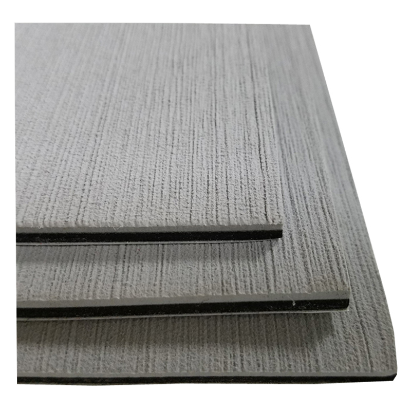
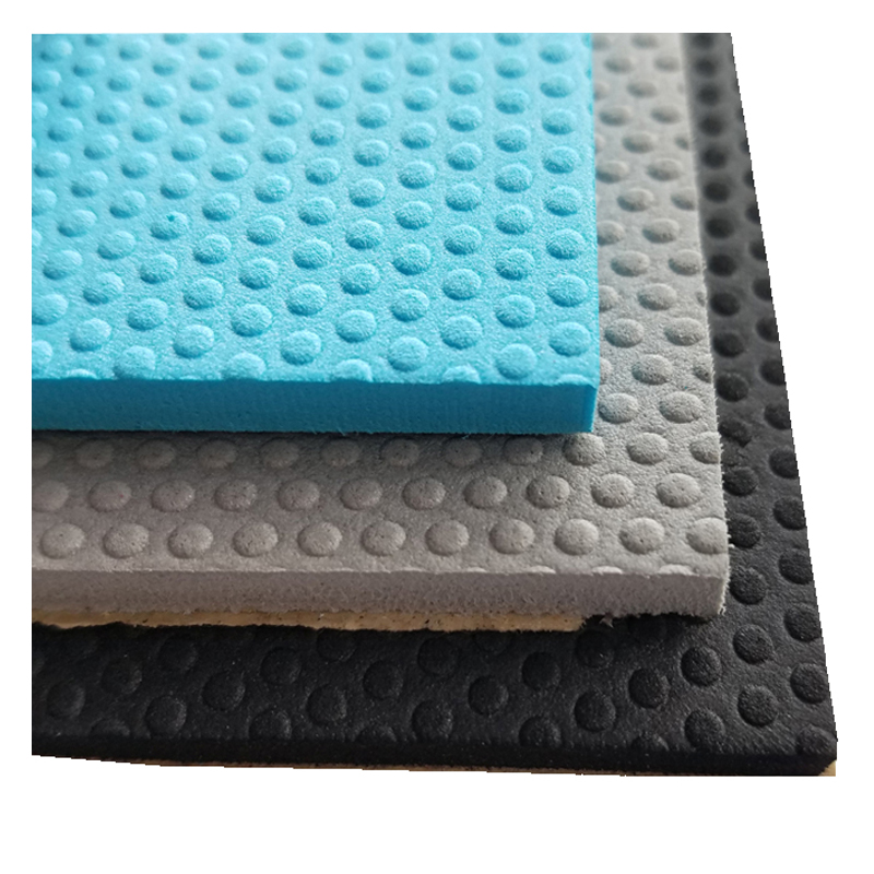
EVA Boat Flooring is a new type marine sheet flooring for boat or yacht. Made from marine grade UV-resistant, closed cell EVA foam material, it is waterproof, antibacterial, comfortable, durable and non-skid.
Basically, the boat flooring has two different textures available, which is brushed and embossed. The sheets can be cut into size to fit the shape of boat decking, then peel the adhesive on the backing and stick it.


Normally the EVA marine sheet can be applied on the boat decking, or with a thicker material, it can be applied as helm station pad, seat pad, or coming bolster pad. What's more, it can be also applied on the edge of swimming pool, cause it can provide a good traction and safety when the feet is wet.

Eva Boat Flooring,Eva Yacht Flooring,Marine Sheet,Diy Boat Flooring,Boat Floor Mat,Boat Mat
Huizhou City Melors Plastic Products Co., Limited , https://www.foampioneer.com


